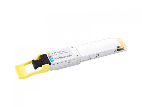
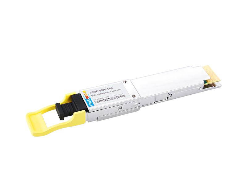
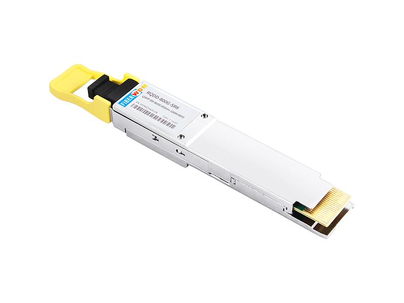
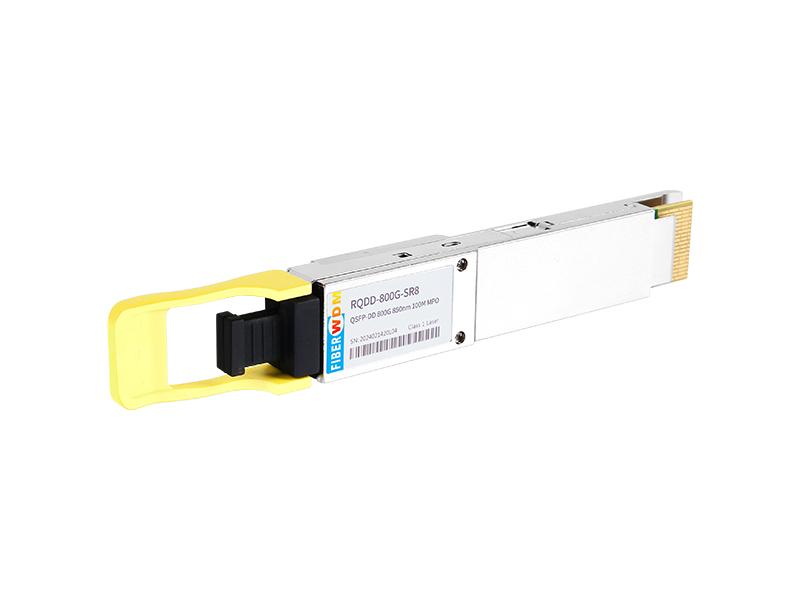

800G QSFP-DD SR8 850nm 100m MPO-16 APC
RQDD-800G-SR8
Applications
1.General Description
RQDD-800G-SR8 is a Eight-Channel, Parallel, Pluggable, Fiber-Optic QSFP-DD for 800Gigabit Ethernet applications. This transceiver is a high performance module for short-reach data communication and interconnect application. It integrates eight data lanes in each direction with 8x53.125GBd. The transmission distance of QSFP-DD SR8 is up to 60 meters over OM3 MMF or 100 meters over OM4 MMF. This module is designed to operate over multimode fiber systems using a nominal wavelength of 850nm.
2. Absolute Maximum Ratings and Recommended Operating Conditions
Table 2.1 Absolute Maximum Ratings
|
Parameter |
Symbol |
Min |
Max |
Unit |
|
Storage Temperature |
Ts |
-40 |
85 |
°C |
|
Case Operating Temperature |
Top |
0 |
70 |
°C |
|
Relative Humidity (non-condensation) |
RH |
15 |
85 |
% |
|
Supply Voltage |
Vcc |
-0.5 |
3.6 |
V |
|
Receiver Damage Threshold, per Lane |
PRdmg |
5 |
|
dBm |
Table 2.2 Recommended Operating Conditions
|
Parameter |
Symbol |
Min |
Max |
Unit |
|
Operating Case Temperature |
Top |
0 |
70 |
°C |
|
Relative Humidity (non-condensation) |
RH |
15 |
85 |
% |
|
Power Supply Voltage |
Vcc |
3.135 |
3.465 |
V |
|
Total Power Consumption1 |
Pc |
- |
14 |
W |
|
Supply Current |
|
|
4.46 |
A |
|
Bit Rate |
BR |
|
850 |
Gbps |
|
Fiber Length on OM3 MMF |
|
|
60 |
m |
|
Fiber Length on OM4 MMF |
|
|
100 |
m |
|
I2C Clock Frequency |
0 |
|
400 |
kHz |
Notes:
1.Under condition of 3.465V operating supply voltage, and 70℃ case temperature.
3. Optical Specification
3.1 Optical Transmitter
Table 3.1 Transmitter Optical Interface
|
Parameter |
Symbol |
Min |
Typical |
Max |
Unit |
|
|
|
Data rate per lane |
DR |
|
53.125 |
|
GBd |
|
|
|
Modulation format |
|
PAM4 |
|
||||
|
Center Wavelength 1 |
λ |
840 |
860 |
868 |
nm |
||
|
RMS spectral width |
σ |
|
|
0.6 |
nm |
||
|
Average Launch power, each lane |
Pavg |
-4.6 |
|
4 |
dBm |
||
|
Optical Power OMA, each Lane,max |
POMA |
3.5 |
dBm |
||||
|
OMAouter, each lane min |
max (TECQ, TDECQ) <1.8 dB |
max [-2.6 , max(TECQ,TECQ) – 4.4] |
dBm |
||||
|
1.8 < max (TECQ, TDECQ) < 4.4 dB |
|||||||
|
Transmitter and dispersion eye closure (TDECQ), each lane |
TDECQ |
|
|
4.4 |
dB |
||
|
Transmitter eye closure for PAM4 (TECQ), each lane |
TECQ |
|
|
4.4 |
dB |
||
|
Extinction ratio |
ER |
2.5 |
|
|
dB |
||
|
Transmitter power excursion, each lane |
|
|
|
2.3 |
dBm |
||
|
Optical Return Loss Tolerance |
ORLT |
|
|
14 |
dB |
||
|
Optical Power for TX DISABLE |
|
|
|
-30 |
dBm |
||
|
Encircled fluxb2 |
|
≥86% at 19 um ≤30% at 4.5 um |
|
||||
Notes:
1. Defined according to the performance of the laser used.
2. Measured into type A1a.2 or type A1a.3, or A1a.4, 50 um fiber, in accordance with IEC 61280-1-4.
3.2 Optical Receiver
Table 3.2 Receiver Optical Interface
|
Parameter |
Symbol |
Min |
Typical |
Max |
Unit |
|
|
Data rate per lane |
BR |
|
53.125 |
|
GBd |
|
|
Modulation format |
|
PAM4 |
|
|||
|
Center Wavelength |
λ |
842 |
850 |
948 |
nm |
|
|
Damage threshold |
|
5 |
|
|
dBm |
|
|
Average receive power, each lane |
|
–6.4 |
|
4 |
dBm |
|
|
Receive power, each lane (OMAouter) |
|
|
|
3.5 |
dBm |
|
|
Receiver reflectance |
Rr |
|
|
–15 |
dB |
|
|
Receiver sensitivity, each lane1 |
|
RS = max (-4.6 , TECQ – 6.4) |
dBm |
|||
|
Stressed receiver sensitivity, each lane |
|
|
|
–2 |
dBm |
|
|
Rx LOS |
Assert |
|
-15 |
|
|
dBm |
|
De-assert |
|
|
|
-7.5 |
dBm |
|
|
Hysteresis |
|
0.5 |
|
5 |
dB |
|
Notes:
1. Receiver sensitivity is informative and is defined for a transmitter with a value of TECQ. Measured with conformance test signal at TP3 for BER = 2.4E-4 Pre-FEC.
4.Electrical Specification
Table 4.1 Electrical Specifications
|
Parameters |
Min |
Typical |
Max |
Unit |
|
Pre FEC Bit Error Ratio |
|
|
2.4E-4 |
|
|
Post FEC Bit Error Ratio |
|
|
1E-12 |
|
|
Transmitter (each Lane) |
||||
|
Differential pk-pk Input Voltage tolerance |
750 |
|
|
mV |
|
Differential Termination Mismatch |
|
|
10 |
% |
|
Eye height |
10 |
|
|
mV |
|
Common-mode to differential-mode return loss |
IEEE802.3ck Equation (120G–1) |
dB |
||
|
Vertical eye closure |
|
|
12 |
dB |
|
Effective return loss |
7.3 |
|
|
dB |
|
Transition Time |
10 |
|
|
ps |
|
Receiver (each Lane) |
||||
|
Differential data output swing |
300 |
|
900 |
mVpp |
|
Differential termination mismatch |
|
|
10 |
% |
|
Eye height |
15 |
|
|
mV |
|
Vertical eye closure |
|
|
12 |
dB |
|
Common-mode to differential-mode return loss |
IEEE802.3ck Equation (120G–1) |
|
||
|
Effective return loss |
8.5 |
|
|
dB |
|
Transition time |
8.5 |
|
|
ps |
5. Ordering Information
|
Part Number |
Temperature Range |
Distance |
Fiber Type |
E/O |
O/E |
|
RQDD-800G-SR8 |
0 to 70℃ |
100m |
MMF |
VCSEL 850nm |
PIN |
相关的标签 :
想知道这个产品吗?
如果您对我们的产品感兴趣并想了解更多详细信息,请在此处留言,我们将尽快答复您。
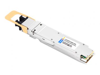 800G OSFP SR8 MM MPO12 Optical Transceiver IB
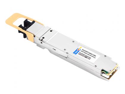 800G OSFP DR8 SM MPO12 Optical Transceiver IB
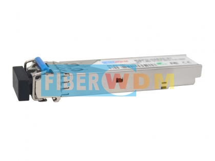 1.25G DWDM SFP Optical Transceiver
 万兆上行千兆管理型POE交换机 FW5700-24GP-4TF
 16路 (32波) 单纤双向 DWDM 带红蓝光 波分复用设备
 千兆10/100/1000M 1光1电 光纤收发器
 100G CFP转QSFP28转换模块 带FEC

地址 : 广州市花都区花山镇菊花石大道128号京东智能产业园6栋901
电话 : +86 15989256178
Whatsapp : 15989256178
电子邮件 : sales@fiberwdm.com
Skype : 15914235380