

Features:
Applications:
Transceiver Types:


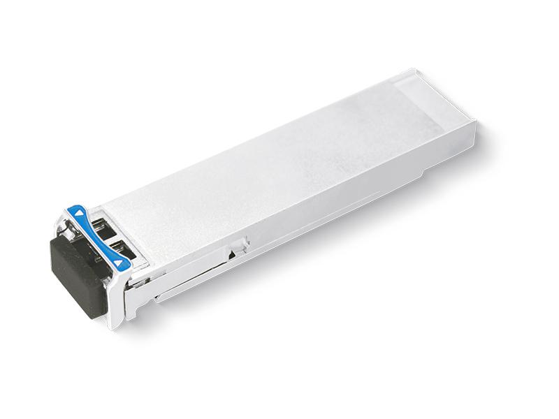
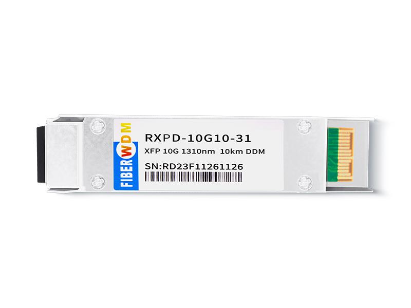
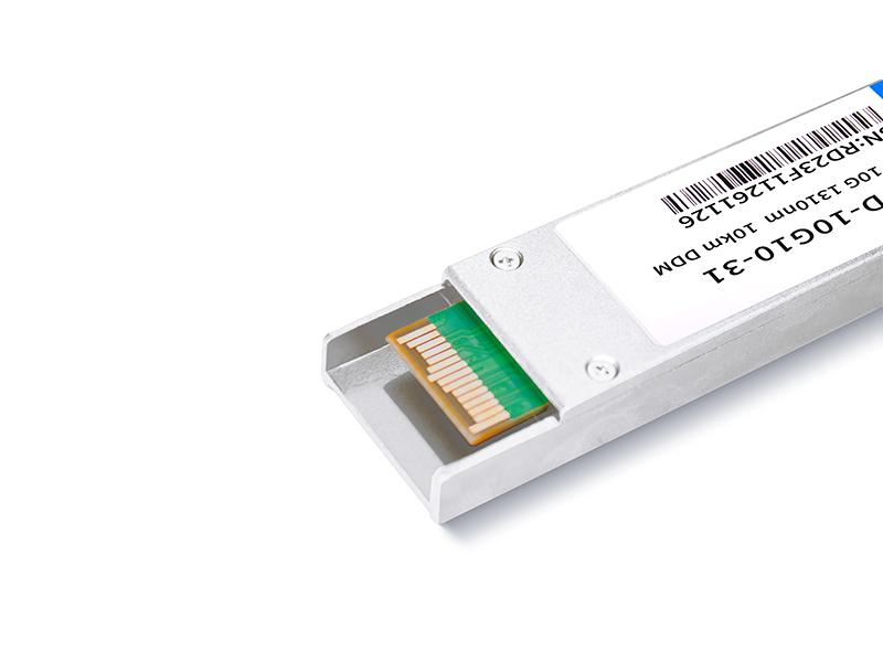
XFP 10G 1310nm 10km Transceiver
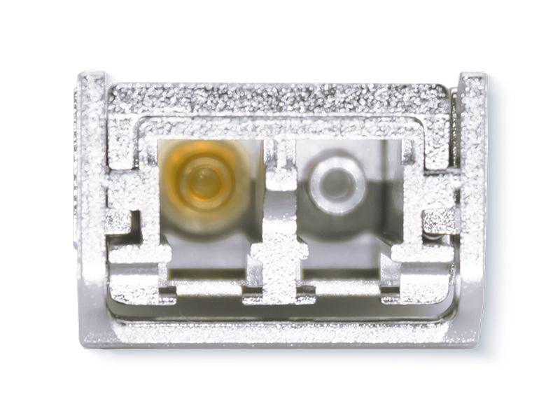
Hot Pluggable, Duplex LC, 1310nm, DFB LD, Single mode
RXPD-10G10-31

Description:
FIBERWDM’s RXPD-10G10-31 Small Form Factor 10Gb/s (XFP) transceivers are compliant with the current XFP Multi-Source Agreement (MSA) Specification. They comply with 10-Gigabit Ethernet 10GBASE-LR/LW per IEEE 802.3ae and10GFiber Channel 1200-SM-LL-L. Digital diagnostics functions are available via a 2-wire serial interface, as specified in the XFP MSA.
Absolute Maximum Ratings
|
Parameter |
Symbol |
Min |
Max |
Unit |
|
Storage Temperature |
TST |
-40 |
+85 |
℃ |
|
Case Operating Temperature |
TIP |
0 |
+70 |
℃ |
|
Supply Voltage |
VCC3 |
-0.5 |
+4.0 |
V |
Electrical Characteristics (TOP= 0 to70 °C)
|
Parameter |
Symbol |
Min |
Typ |
Max |
Unit |
Note |
|
Supply Voltage |
Vcc3 |
3.13 |
|
3.45 |
V |
|
|
Supply Current |
Icc3 |
|
|
400 |
mA |
|
|
Module total power |
P |
|
|
2 |
W |
|
|
Transmitter |
||||||
|
Input differential impedance |
Rin |
|
100 |
|
Ω |
1 |
|
Differential data input swing |
Vin,pp |
150 |
|
820 |
mV |
|
|
Transmit Disable Voltage |
VD |
2.0 |
|
Vcc |
V |
|
|
Transmit Enable Voltage |
VEN |
GND |
|
GND+ 0.8 |
V |
|
|
Transmit Disable Assert Time |
T_off |
|
|
100 |
ms |
|
|
Tx Enable Assert Time |
T_on |
|
|
100 |
ms |
|
|
Receiver |
||||||
|
Differential data output swing |
Vout,pp |
300 |
500 |
850 |
mV |
|
|
Data output rise time |
tr |
|
|
35 |
ps |
2 |
|
Data output fall time |
tf |
|
|
35 |
ps |
2 |
|
LOS Fault |
VLOS fault |
Vcc – 0.5 |
|
Vcc HOST |
V |
3 |
|
LOS Normal |
VLOS norm |
GND |
|
GND+0.5 |
V |
3 |
|
Power Supply Rejection |
PSR |
See Note 4 below |
4 |
|||
Notes
1. After internal AC coupling.
2. 20 – 80 %
3.Loss of Signal is open collector to be pulled up with a 4.7k – 10kohm resistor to 3.15 – 3.6V. Logic 0 indicates normal operation; logic 1 indicates no signal detected.
4. Per Section 2.7.1. in the XFP MSA Specification.
Optical Parameters (TOP= 0 to70°C)
|
Parameter |
Symbol |
Min |
Typ |
Max |
Unit |
Ref. |
|
Transmitter |
||||||
|
Operating Date Rate |
BR |
9.95 |
|
11.3 |
Gb/s |
|
|
Bit Error Rate |
BER |
|
|
10-12 |
|
|
|
Maximum Launch Power |
PMAX |
-8.2 |
|
0.5 |
dBm |
1 |
|
Optical Wavelength |
λ |
1260 |
1310 |
1355 |
nm |
|
|
Optical Extinction Ratio |
ER |
3.5 |
|
|
dB |
|
|
Spectral Width@-20dB |
Δλ |
|
|
1 |
nm |
|
|
Sidemode Suppression ratio |
SSRmin |
30 |
|
|
dB |
|
|
Rise/Fall Time (20%~80%) |
Tr/Tf |
|
|
35 |
ps |
|
|
Average Launch power of OFF Transmitter |
POFF |
|
|
-30 |
dBm |
|
|
Tx Jitter |
Txj |
Compliant with each standard requirement |
|
|||
|
Optical Eye Mask |
|
IEEE802.3ae |
2 |
|||
|
Receiver |
||||||
|
Operating Date Rate |
BR |
9.95 |
|
11.3 |
Gb/s |
|
|
Receiver Sensitivity |
Sen |
|
|
-12.6 |
dBm |
2 |
|
Maximum Input Power |
PMAX |
0 |
|
|
dBm |
2 |
|
Optical Center Wavelength |
λC |
1260 |
|
1355 |
nm |
|
|
Receiver Reflectance |
Rrx |
|
|
-12 |
dB |
|
|
LOS De-Assert |
LOSD |
|
|
-13 |
dBm |
|
|
LOS Assert |
LOSA |
-30 |
|
|
dBm |
|
|
LOS Hysteresis |
LOSH |
0.5 |
|
5 |
dB |
|
Notes:
1. The optical power is launched into SMF.
2. Measured with a PRBS 231-1 test pattern @10.3125Gbps BER<10-12.
Pin Assignment
Diagram of Host Board Connector Block Pin Numbers and Name

Mechanical Dimensions

想知道这个产品吗?
如果您对我们的产品感兴趣并想了解更多详细信息,请在此处留言,我们将尽快答复您。
 10G DWDM SFP+ Optical Transceiver
10G SFP+ Optical Transceiver
10G CWDM SFP+ Optical Transceiver
10G DWDM SFP+ Optical Transceiver
10G SFP+ Optical Transceiver
10G CWDM SFP+ Optical Transceiver
 10G BIDI SFP+ Optical Transceiver
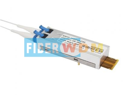 10G DWDM SFF 40km Transceiver -40℃ To 85℃
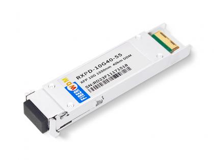 XFP 10G 1550nm 40km Transceiver
 XFP 10G 1550nm 80km Transceiver
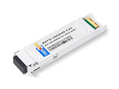 XFP 10G DWDM 40km Transceiver

地址 : 广州市花都区花山镇菊花石大道128号京东智能产业园6栋901
电话 : +86 15989256178
Whatsapp : 15989256178
电子邮件 : sales@fiberwdm.com
Skype : 15914235380